Scalable Multi-Controller Coordination in Periplus via Border-Switch Forwarding Graphs
July 21, 2026
Abstract
In-band SDN control planes, where control traffic shares the data-plane infrastructure, suit wide-area, resource-constrained deployments—such as rural backbones—that cannot afford a dedicated control network. Partitioning such a network across multiple controllers improves scalability but raises a coordination challenge that in-band designs have largely ignored: controllers must discover one another and exchange state in-band, and switches must recover when their controller fails, all without forwarding state that grows with the number of controllers.
This paper presents the multi-controller coordination plane of Periplus, an in-band control plane whose single-controller design is developed in a companion paper. Periplus controllers discover their neighbors through Controller Advertisement (C-Adv) messages and build inter-controller routes incrementally: each border switch inserts a partial forwarding graph covering only the next domain, so per-controller forwarding state is confined to border switches and never distributed across the interior of an intermediate domain. The same C-Adv mechanism reattaches a switch to a surviving controller after a controller failure.
We evaluate a Ryu-based implementation in Mininet, including a 96-switch, 5-controller scenario. Per-switch flow-table state is set by a switch’s role rather than by network size—interior occupancy stays constant as controllers are added—partitioning scales bootstrap to networks of around a hundred switches, and inter-controller discovery converges within seconds. The design needs no switch-firmware modifications: it runs on stock Open vSwitch, using only its built-in Nicira extensions for Network Service Header (NSH) encapsulation.
1 Introduction↩︎
Despite significant advances in telecommunications infrastructure, many rural and underserved regions still lack reliable Internet connectivity [1]. These regions combine low population density, limited income, a shortage of local technical personnel, and scarce complementary power and communications infrastructure. Their service requirements, however, are often similar to those of dense urban areas, so they call for technologies that are simultaneously low-cost, robust, flexible, and easy to deploy and operate.
Software-defined networking (SDN) [2] can bring clear benefits to these networks, but only if some of their specific constraints are met. Because they lack a parallel infrastructure for control or signaling, the control plane must run in-band, sharing the data-plane links it manages [3], [4]. SDN’s centralized control simplifies operation, yet it must be reinforced with robustness and resilience mechanisms so that the network keeps serving users despite the unstable links and frequent topology changes typical of these environments, and continues to operate with little to no human intervention.
An in-band control plane must overcome four challenges that a dedicated control network would not face. First, a switch must attach to the control plane before any forwarding rule exists to carry its own control traffic (bootstrapping). Second, once attached, its control messages must travel over efficient paths that keep per-switch state low (routing). Third, switches must survive link and node failures without waiting for the controller to intervene (failure recovery). Fourth, once the network is large enough to require several controllers, those controllers must stay coordinated over the same in-band substrate they manage (multi-controller coordination).
Earlier proposals for these environments strike different balances: some prioritize adaptability, low cost, and quality at the expense of high complexity [5], while others trade some quality for easier deployment and operation [6]. Periplus was recently proposed as an SDN architecture tailored to these settings. Its single-controller design, presented in [7], addresses the first three challenges: a bootstrap that installs flow rules in only two switches when a switch joins, graph-based source routing with minimal per-switch state, and sub-50 ms failure recovery performed locally at the switch, combining prompt link-failure detection with forwarding alternatives precomputed for each hop. That design, however, assumes a single controller and does not address the fourth challenge. The present paper builds on Periplus to tackle this fourth and least-explored challenge: coordinating multiple controllers over the in-band network.
Partitioning a wide-area network across several controllers improves scalability and keeps control traffic local, but coordinating those controllers in-band is difficult. Controllers must discover one another and exchange switch state over the same network they manage, and a switch must keep reaching a controller when its own fails, all without flooding the network or storing forwarding state that grows with the number of controllers. Existing in-band designs that admit multiple controllers (Section 2) give each controller its own spanning tree or a set of disjoint control paths, so per-switch forwarding state scales with the controller count, eroding the scalability that motivated partitioning in the first place.
This paper contributes a multi-controller coordination mechanism whose per-controller forwarding state is confined to border switches. Periplus controllers discover their neighbors through Controller Advertisement (C-Adv) messages and establish inter-controller routes across domains incrementally: each border switch inserts a partial forwarding graph covering only the next domain, so the routing state needed to reach a remote controller is never distributed across the interior switches of any intermediate domain. The same C-Adv substrate lets a switch recover after a controller failure by re-attaching through a neighboring domain. Because coordination state is confined to domain boundaries, the architecture remains scalable as the number of controllers and switches increases.
Periplus is implemented in Python on the Ryu SDN framework [8], [9] and evaluated through network emulation in Mininet across several multi-controller topologies, including a large-scale scenario with 96 switches and 5 controllers. The results confirm that per-switch forwarding state stays bounded: interior switches hold a constant number of rules regardless of the number of controllers, and additional state appears only at border switches.
The remainder of this paper is organized as follows. Section 2 reviews related work on multi-controller coordination in in-band SDN. Section 3 recaps the single-controller design of Periplus that the multi-controller plane builds on. Section 4 presents the multi-controller coordination mechanism, covering inter-controller discovery, communication, and switch recovery after a controller failure. Section 5 reports an experimental evaluation in Mininet across multi-controller topologies, including the 96-switch, 5-controller scenario. Finally, Section 6 concludes the paper.
2 Related Work↩︎
This paper extends Periplus, an in-band SDN control plane, to operate across multiple controllers. The single-controller design of Periplus (automatic bootstrapping, graph-based source routing, and sub-50 ms failure recovery) and the related work on those three challenges are presented in [7]. This section concentrates on the fourth and least-explored challenge of in-band SDN control planes: coordination among multiple controllers.
For context, we briefly situate the three single-controller challenges. Bootstrapping proposals such as Medieval and Renaissance [10], [11], Sakic et al. [12], FASIC [13], and Wong and Lee [14] achieve plug-and-play attachment but at the cost of network-wide flooding or per-switch state that grows with network size. For routing, source-based approaches such as Amaru [15] reduce forwarding state yet cannot guarantee controller reachability after a failure. For failure recovery, protection schemes such as those of Sharma et al. [16]–[18] reach sub-50 ms recovery but preinstall backup paths on every switch and rely on STP for bootstrap.
Multi-controller coordination. Multi-controller coordination has received comparatively little attention in the in-band control plane literature. Medieval and Renaissance support multiple controllers by having each controller build an additional spanning tree covering all switches in the network, which imposes per-controller forwarding state on every switch. Sakic et al. [12] deploy multiple controller replicas synchronized via RAFT consensus, provisioning disjoint control paths per switch-controller pair; per-switch forwarding state likewise grows with the number of controllers. Holzmann et al. [19] extend Izzy to elastic controller clusters via the Seedling algorithm, which divides controllers into proximity-based groups and assigns a separate Izzy spanning tree per group; however, per-switch forwarding state still scales with the number of controllers. Chan et al. [20] target fast failure recovery in in-band multi-controller OpenFlow networks: a Main Controller and several Standby Controllers collaborate to detect failures through monitoring cycles and reroute traffic by installing new flow entries, provisioning \(K\) disjoint control paths per switch (one from each controller) to guarantee reachability after any single device failure, with average recovery times below 50 ms. Unlike Periplus, recovery there requires explicit coordination between controllers and is not performed locally at the switch. Across these proposals, none jointly addresses fast inter-controller communication and bounded per-switch state overhead in an in-band setting.
Schiff et al. [21] explore an orthogonal approach to controller coordination: using part of the data-plane configuration space as transactional shared memory, implementing atomic compare-and-swap operations via OpenFlow bundling to synchronize distributed controllers.
Panda et al. [22] argue that strong consensus protocols are conceptually inappropriate for network state in distributed SDN controllers, since the physical network is inherently uncertain; they propose eventual correctness instead. Periplus is aligned with this view: it provides the inter-controller communication infrastructure without imposing any consistency model, leaving coordination semantics to the applications above.
Multi-controller coordination thus remains the least explored challenge of in-band SDN control planes, and existing solutions impose forwarding state proportional to the number of controllers on every switch. Periplus departs from this pattern: it uses Controller Advertisement messages and border switches to confine per-controller forwarding state to the switches at domain boundaries, and it provides the inter-controller communication infrastructure without mandating any consistency model. The following sections describe this mechanism and evaluate how it scales Periplus across multiple controllers.
3 Background: Single-Controller Periplus↩︎
This section recaps the single-controller design of Periplus to the extent needed to follow its multi-controller extension; the full design, with its protocols, tables, and message-overhead analysis, is presented in [7]. Periplus rests on three core design choices for the single-controller case: anchor-relayed bootstrap, graph-based source routing, and packet-encoded failure recovery. A fourth mechanism, Controller Advertisement (C-Adv) messages, serves as a cross-cutting discovery substrate. Multi-controller operation (Section 4) extends these choices through C-Adv messages and border switches.
We assume that node communication interfaces, wired or wireless, are based on IEEE 802 link technologies, so that each interface is identified by a unique 48-bit MAC address, and that links are bidirectional. Switches are denoted \(si\) with \(cj\) reserved for the OVS switch co-located with the controller (the root switch).
3.1 Bootstrap↩︎
Periplus bootstraps the control plane incrementally: switches attach one by one, each relying on a neighboring managed switch to relay its connection requests. Before it can connect, an unmanaged switch must learn the port toward the controller, which it caches in a soft-state register (\(reg9\)) with a short hard timeout. It learns this port from whichever controller-attributable signal arrives first: a proxy-ARP reply from a managed neighbor (the anchor) answering on the controller’s behalf, or a Controller Advertisement re-forwarded by a managed neighbor (Section 3.4). Both can only reach an unmanaged switch from the controller side, so the ingress port on which they arrive is the upstream port. The two triggers cover complementary cases: the ARP reply handles a cold start, and the C-Adv handles a warm restart, when a previously managed switch still caches the controller’s MAC address, issues no ARP request, and can relearn its upstream port only from a neighbor’s C-Adv. The switch sends its TCP SYN through the learned port; if none has been learned the SYN is dropped, and if the signals stop the cached entry expires and the switch reverts to the unmanaged state. The controller identifies the new switch from the Ethernet source address of its SYN and installs the forwarding flows that place it in the managed state, updating only two switches rather than every switch on the path to the controller; the full preconfigured rule set is given in [7]. In a multi-controller deployment this anchor relay operates within each controller domain, and border switches extend it across domain boundaries (Section 4).
3.2 Forwarding based on graphs↩︎
Periplus routes control traffic with the Slick Packets approach [23]: a forwarding graph, an acyclic subgraph of the topology embedded in the packet headers between the L2 and L3 layers using NSH [24] (realized with OVS’s Nicira extensions [25]), encodes a primary path \(P\) and, at each hop \(i\), an ordered list of up to \(K_i\) alternative paths as output-port sequences. The controller computes \(P\) with Dijkstra and derives source-disjoint alternatives by iteratively pruning and re-running it. A switch that cannot forward through its primary port falls over locally to the first reachable alternative, with no controller involvement. Only the root switch co-located with the controller maintains routing state for all switches in its domain; every other switch stores only the path to its own controller. This domain-local property is what the multi-controller plane builds on: inter-domain routes are assembled from partial graphs inserted by border switches, so no interior switch ever holds routing state for a remote controller (Section 4).
3.3 Monitoring ports↩︎
Each switch monitors its links with two complementary detectors: Bidirectional Forwarding Detection (BFD) [26], used together with OpenFlow select group tables [27], and Input Traffic Detection (ITD), based on OpenFlow Echo Request/Reply messages and learning flows. On detecting a link or node failure, a switch immediately reroutes along an encoded alternative from the packet’s graph, meeting carrier-grade (sub-50 ms) recovery without contacting the controller.
3.4 Link Discovery Protocol↩︎
Once switches are managed, the controller knows the tree of links that connect it to them, but not the redundant links that can serve as alternatives. Periplus discovers these through Controller Advertisement (C-Adv) messages. The controller periodically issues a single Packet-Out to the root switch, which floods it; each switch floods a C-Adv only on first reception, suppressing duplicates with a short-lived learning flow whose hard timeout is shorter than the C-Adv period, and reports the reception to the controller with a Packet-In. Each managed switch encodes its own identity and egress port into the header of every C-Adv it forwards, so the controller can identify both endpoints of each discovered link. This controlled flooding avoids broadcast storms and reduces the controller to a single Packet-Out per discovery round; its message-overhead advantage over standard link-discovery protocols is analyzed in [7]. C-Adv is the substrate the multi-controller plane reuses: it underpins both inter-controller discovery and the recovery of switches after a controller failure (Section 4).
4 Multiple Controllers↩︎
Periplus is designed to support multiple controller instances. Each controller manages a disjoint set of switches, known as its domain; a switch with a link into another controller’s domain is a border switch, through which inter-controller traffic transits from one domain to the next. A switch is assigned to a controller as a direct consequence of the bootstrap mechanism of Section 3.1: the nearest managed neighbor relays the booting switch’s TCP SYN toward its own controller, yielding a first-come, first-served (FCFS) assignment to typically the nearest controller. Disjointness is enforced implicitly, since once the routing flows are installed the switch’s control traffic is directed exclusively through its anchor to a single controller; if the switch later reboots, it re-runs the bootstrap procedure and may attach to a different controller if the topology has changed.
This assignment rests on how controllers are addressed. All controllers share a single anycast address, so an unmanaged switch attaches to whichever controller its bootstrap signals reach first—typically the nearest—without needing to know which controller that is. In addition, each controller owns a distinct unicast address that identifies it to the other controllers; the inter-controller discovery and communication mechanisms described below rely on these addresses to tell controllers apart and route between them. These unicast addresses are used only among controllers: a switch never needs to know the unicast address of any controller, and reaches the control plane solely through the shared anycast address.
This section describes how controllers discover and communicate with neighbor controllers, how this mechanism is extended to non-neighbor controllers, and how switches recover from a controller failure.
4.1 Communication between neighbor controllers↩︎
C-Adv messages are used to discover other controllers. The propagation of C-Adv messages follows the controlled flooding mechanism described in Section 3.4. Since multiple controllers coexist within the same network, when a switch forwards a C-Adv through an interface connected to a switch managed by another controller, the receiving switch generates a Packet-In message to its own controller and does not forward the C-Adv further. This mechanism enables a controller to detect the presence of another controller in the network.
Figure 1 illustrates a network with two controllers. Switches managed by controller 1 are shown in yellow, while those managed by controller 2 are shown in blue. As depicted in Fig. 1 (a), switch \(s1\) receives a C-Adv message generated by controller 2 and generates a Packet-In to controller 1. Upon receiving this message, controller 1 becomes aware of controller 2’s presence, and then controller 1 installs a new flow in \(c1\) (the root switch of controller 1) to reach controller 2 via \(s1\). This flow instructs \(c1\) to embed in packets destined for \(c2\) a forwarding graph whose primary path terminates at port 2 of \(s1\). Figure 1 (b) shows how packets from controller 1 to controller 2 are forwarded through controller 1’s domain using the embedded graph until reaching \(s1\). Between \(s1\) and \(s2\), packets do not carry the graph; however, \(s2\) is a border switch with a flow installed to embed the forwarding graph for its own domain, and therefore inserts the graph that enables the packet to reach controller 2.

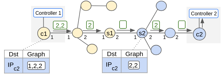
Figure 1: Inter-controller discovery via C-Adv on a two-controller topology: (a) \(s1\) receives a C-Adv from controller 2 and reports the link to controller 1; (b) controller 1 forwards a packet to controller 2 using the embedded forwarding graph..
Analogously, when \(s2\) receives a C-Adv from controller 1 and generates a Packet-In to its own controller, controller 2 installs a new flow rule in \(c2\) to reach controller 1.
4.2 Communication between non-neighbor controllers↩︎
The mechanism described above operates directly when controller domains are neighbors. It generalizes to non-neighboring controllers through Algorithm 2.

Each C-Adv carries a list of all controllers known to the sender, each entry accompanied by its \(\mathit{learnt\_from}\) path vector. Upon reception, the local controller processes the sending controller as a direct neighbor, then iterates over the payload to discover non-neighboring controllers. Three conditions guard each entry: the controller’s own IP is skipped; a direct neighbor cannot be downgraded to non-neighbor status; and any entry whose \(\mathit{learnt\_from}\) list already contains the local controller’s IP is discarded. This last condition prevents routing loops by the same principle as the AS_PATH attribute in BGP [28]: just as a BGP router rejects a route whose AS_PATH already contains its own AS number, a controller rejects an entry that has already passed through it.
Forwarding graphs are computed using Dijkstra’s algorithm on the local topology graph: the primary path is the shortest path within the local domain to the border switch adjacent to the destination controller’s domain, and for each hop, an alternative path is computed where one exists. These flows are installed when a new peer controller is discovered, following the same soft-state principle as the \(\mathit{alive}\) counter.
This locality has a direct consequence for state distribution. Non-border switches require no state beyond the path to their own controller—the same property established in Section 3.2 for the single-controller case. Additional state is installed only at border switches that serve as entry points for transit between pairs of neighbor controllers (Algorithm 2, line 27): each such switch stores a single forwarding graph per transit destination, encoding only the short, local path within its own domain from the entry border to the exit border switch facing the next domain. This guarantees transit without distributing state across the domain interior.
Liveness is maintained through a soft-state \(\mathit{alive}\) counter, following the same design principle as RSVP [29]: entries are periodically refreshed by incoming C-Adv messages and expire silently when refreshes stop. When a controller fails, its C-Adv messages cease, all entries referencing it are no longer refreshed, and they eventually expire across the network.
Fig. 3 illustrates Algorithm 2 for a three-controller topology. Controller 1 is a direct neighbor of both controller 2 and controller 3. It advertises both in its C-Adv. Controllers 2 and 3 learn of each other from controller 1’s payload and install the required flows; the loop-detection condition prevents each from re-accepting the other’s entry via controller 1.

Fig. 4 uses the same three-controller topology as Fig. 3, showing the forwarding state each controller holds after discovery completes; in each subfigure, switches belonging to other domains are collapsed into black segments. As shown in Fig. 4 (a) and Fig. 4 (b), controllers 2 and 3 each install a new flow in their root switches (\(c2\) and \(c3\)) to embed the connectivity graph required to reach the newly discovered non-neighboring controller. Controller 1 also installs new flows in its border domain switches: as illustrated in Fig. 4 (c), a new flow in switch \(s12\) to reach controller 3, and new flows in switches \(s23\) and \(s22\) to reach controller 2.


Figure 4: Non-neighbor controller discovery (same topology as Fig. 3); switches in other domains are collapsed into black segments..
This mechanism resembles a segment-routing approach [30], but the forwarding graph is installed incrementally rather than at the ingress: each border switch adds the segment crossing its own domain. For example, a message from controller 2 to controller 3 in the topology of Fig. 3 carries \(P=[2,1]\) from \(c2\) to border switch \(s12\), then \(P=[3,1]\) across controller 1’s domain to the exit border switch \(s33\), where the local segment within controller 3’s domain is added. The full end-to-end path is never encoded at any single point, which scales more effectively than ingress-only encoding across multiple domains containing large numbers of switches.
4.3 Controller Failure Recovery↩︎
Unlike the link and node failures of Section 3.3, which a switch survives locally by rerouting to an alternative path toward the same controller, a controller failure leaves the switch unable to reach its controller at all, so it must attach to a surviving one. The affected switches recover through the event-driven procedure of Algorithm 5, which reuses the preconfigured bootstrap rules of Section 3.1.

The controller installs the routing flows with a hard timeout and refreshes them periodically. Recovery therefore requires no explicit failure detection on the switch’s part: it is triggered implicitly when the controller fails and stops refreshing these flows, so they expire and return the switch to the unmanaged state of Section 3.1 with no upstream port cached (\(reg9 = 0\)). The two learning signals that drive initial attachment then reattach the switch, now to a surviving controller. As at bootstrap, the C-Adv path takes priority: a Controller Advertisement from a managed neighbor sets \(reg9\) and suppresses the ARP path, which activates only when no C-Adv has arrived and the ARP cache holds no controller entry (the warm-restart case of Section 3.1). Both paths converge at the TCP SYN, re-running the attachment of Section 3.1 against the surviving controller, which installs routing flows and brings the switch into its domain.
5 Evaluation↩︎
This section evaluates the multi-controller plane of Periplus along the two properties its design promises (Section 1): that per-controller forwarding state stays confined to border switches, and that partitioning a network across controllers scales the control plane to networks of around a hundred switches, with each controller managing only a small domain. We first measure how bootstrap time scales as a network is partitioned across an increasing number of controllers (Section 5.1). We then evaluate the coordination mechanism in action: the time for controllers to discover one another (Section 5.2) and the time for switches to recover after a controller fails (Section 5.3). Finally, we measure the per-switch flow-table footprint as a function of each switch’s role, confirming that coordination state is bounded at domain boundaries (Section 5.4).
The experimental setup follows that of [7]. Topologies are emulated with Mininet 2.3 [31], switches are OVS 2.15, and Periplus runs on the Ryu 4.32 SDN framework, on an Ubuntu 24.04 system with an AMD Ryzen 7 4800H CPU and 64 GB of RAM.
As in the single-controller evaluation, each OVS instance runs in its own network namespace and in secure mode (fail-mode=secure), so that a switch cannot reach any controller until a neighbouring switch is itself managed, reproducing a pure
in-band control plane. Unless otherwise noted, each experiment is repeated twenty times.


We evaluate the multi-controller variants of Fig. 6, derived from the single-controller topologies of [7] by placing controllers at selected switches. Two additional Mesh variants (2c_Mesh and 3c_Mesh) are obtained from the 4c_Mesh topology by removing controllers. The large-scale topology of Fig. 7 (Large, 96 switches) is tested with 2, 3, 4, and 5 controllers.
5.1 Bootstrap scaling across controllers↩︎
Periplus bootstraps incrementally, so a switch can begin attaching only once a neighbouring switch is managed: bootstrap time is governed by the diameter of the region a controller must reach, not by the total number of switches [7]. Partitioning a network across several controllers exploits this directly, since each controller bootstraps only its own domain. Adding controllers shrinks the per-controller diameter and shortens the critical path, letting the control plane scale to networks far larger than a single controller could bootstrap quickly. This scaling is what the bounded per-controller state of Section 5.4 pays for: because coordination state stays at domain boundaries, partitioning adds controllers without inflating per-switch state.
We measure the wall-clock bootstrap time, the interval from the first TCP SYN received at any controller to the moment the last switch is marked managed across all controller logs, on the Large topology of Fig. 7 (96 switches) partitioned across 2, 3, 4, and 5 controllers. We use twenty repetitions per configuration on the patched OVS build (Section 5.3 describes the patch).

Fig. 8 shows the result. The median wall-clock falls from \(14.8\) s with two controllers to \(10.2\) s with three, and then flattens (\(9.7\) s at four, \(10.4\) s at five): once the per-controller diameter reaches its minimum, adding controllers yields no further gain. A 96-switch network thus bootstraps in around ten seconds once it is partitioned into three or more domains, confirming that partitioning keeps each controller’s domain small—a dozen switches here—while the network as a whole scales to nearly a hundred. The within-configuration spread reflects the first-come-first-served variability in how many switches each controller ends up managing (Section 4).
5.2 Inter-controller discovery time↩︎
In a multi-controller deployment, no inter-controller coordination can begin until every controller has discovered every other controller. The convergence time of this initial discovery phase is therefore the floor on how quickly the multi-controller plane becomes fully operational. The C-Adv-based mechanism of Section 4 performs this discovery implicitly: each controller learns about a peer the first time one of its managed switches forwards a C-Adv originated by that peer. We measure how long that learning takes in practice.
We run three multi-controller scenarios (2c_Simple, 4c_Mesh, and the 5-controller large-scale topology), and for each run we record the interval between the moment the last controller is launched and the latest “first-time-learned” event across all controllers. We use twenty repetitions per scenario.

Fig. 9 shows the distributions. Patched-build medians are \(4.2\) s (2c_Simple), \(5.9\) s (4c_Mesh), and \(3.6\) s (5c_Large); stock-build medians are \(10.2\) s, \(11.8\) s, and \(8.0\) s, \(2.0\)–\(2.4\times\) slower because the cascade-bound bootstrap of Section 5.1 delays the first C-Adv from reaching a peer’s domain. The 5c_Large topology discovers faster than 4c_Mesh despite having more controllers, because its richer connectivity offers more paths for C-Adv propagation. Discovery cost depends on the inter-domain diameter, not on the number of alternative paths \(K\): each controller needs only one C-Adv per peer, and the number of C-Adv messages per beacon period stays constant per managed switch. Each C-Adv’s payload does grow with the number of controllers—it carries one entry, a controller and its path vector, per known controller—but for the handful of controllers these deployments use, this list fits comfortably within a single packet, so the added overhead is negligible.
5.3 Controller failure recovery↩︎
When a controller fails, the switches it managed are momentarily orphaned and must rejoin the control plane through a surviving controller. The controller-failure recovery procedure of Section 4.3 keeps this outage short: a switch whose flow entries expire reverts to its preconfigured initial rules, learns its new upstream port from the next C-Adv that arrives, and re-runs the bootstrap procedure against a surviving controller. We quantify how long that sequence takes end to end. Data-plane recovery from link and switch failures under a single controller is evaluated in [7]; here the failure is the controller itself.
The experiment uses the 4c_Mesh topology. The controller colocated in c4 is killed, and the four switches it managed (s41–s44) must reattach via C-Adv to a surviving controller (colocated in c1, c2, or c3), see Fig. 10.

Because s42, s43, and s44 reach a surviving controller only through s41 or each other, recovery proceeds as a daisy chain in which each switch completes its own OpenFlow handshake only after its upstream neighbour on the new path is itself managed. The metric is the wall-clock recovery time: the interval between the kill of the controller colocated in c4 and the moment the last affected switch is marked managed on its new controller. We use twenty repetitions per OVS variant.

Fig. 11 shows a median recovery of \(10.2\) s on the patched OVS build: this is the Periplus reattach cost, the time to install the flows for the four-switch daisy chain plus the BFD and C-Adv detection latency. The default build is roughly three times slower (median \(35.5\) s), but the gap is entirely OVS-side. Stock OVS keeps a switch convinced its dead controller is still alive for several seconds, through hardcoded floors on its inactivity-probe and reconnect-backoff timers and, dominant here, a definition of connection “activity” that counts queued-but-unacknowledged messages as peer liveness. The optional rconn patch, described in [7], removes these obstacles.
5.4 Flow-table occupancy by switch role↩︎
The amount of per-switch forwarding state a controller must install bounds how large a network can grow before a single switch’s flow table becomes the limit. Periplus’s central claim is that this state is local: an interior switch holds only the forwarding graph toward its own controller, while a border switch additionally holds one transit graph per peer controller it relays for. This is the property that makes the bootstrap scaling of Section 5.1 possible: because coordination state is confined to domain boundaries, a network can be partitioned across more controllers without inflating the state on any interior switch. We test the claim by counting the distinct \((table, priority, match)\) rules the controller installs on each switch, grouped by role: root (the controller’s co-located switch), border (a switch that received at least one transit-graph install), and interior. We sweep the Mesh family from one to four controllers, with five repetitions per configuration.
Fig. 12 confirms the locality claim. Interior occupancy is constant at \(\approx\)42 rules per switch regardless of the number of controllers.

Border switches sit at \(\approx\)52 rules, the interior baseline plus a single peer’s transit subgraph, and appear only once a domain must relay for a non-adjacent peer (with two controllers placed at opposite ends of the Mesh, no switch lands on a transit path, so border switches first appear at three controllers). The root switch holds \(\approx\)27–37 rules, dropping slightly as controllers are added and routing work is shared among peers. None of the three counts depends on the absolute number of switches in the network: per-switch state is set by a switch’s role, not by network size, which is precisely what lets Periplus partition a network across controllers and scale to networks of around a hundred switches. By contrast, the spanning-tree-per-controller designs of Section 2 install one tree on every switch per controller, so their interior state grows linearly with the number of controllers; Periplus keeps it constant.
6 Conclusions and Future Work↩︎
This paper presented the multi-controller coordination plane of Periplus, an in-band SDN control plane whose single-controller design is developed in [7]. Periplus partitions a wide-area network across several controllers while keeping the coordination cost in-band and local: controllers discover one another through Controller Advertisement messages, and inter-controller routes are assembled incrementally from partial forwarding graphs inserted by border switches, so that per-controller forwarding state is confined to the switches at domain boundaries and never distributed across the interior of an intermediate domain.
The Mininet evaluation, including a large-scale scenario with 96 switches and up to five controllers, confirms the two properties this design targets and characterises the coordination mechanism in action. Partitioning scales bootstrap: a 96-switch network is brought under control in around ten seconds once it is split across three or more controllers, since each controller bootstraps only its own domain. Per-switch flow-table occupancy is set by a switch’s role rather than by network size: interior occupancy is constant regardless of the number of controllers, and grows only at border switches, by one transit subgraph per peer controller. Inter-controller discovery converges in 3.6–5.9 s, and a failed controller’s switches reattach to a surviving controller in a median of 10.2 s. The bootstrap, discovery, and recovery figures above are all reported on an optional patched OVS build; the patch addresses stock-OVS reconnect heuristics and is not required by the Periplus design, which otherwise runs unmodified on stock OVS.
Several directions remain open. The evaluation so far relies on Mininet emulation; validating Periplus on a physical testbed—in particular over the resource-constrained links of the rural deployments that motivate it—is an important next step. The current first-come, first-served switch assignment leaves load uneven across controllers; using the switch-count and topology information already exchanged through C-Adv to inform attachment decisions is a natural step toward load-aware controller assignment. Building coordination and consistency protocols, such as eventual-correctness approaches [22], on top of Periplus’s inter-controller communication infrastructure is a further open direction.